Lifting water seems easy.
But the wrong pump choice wastes money and can damage your system.
Let's find the perfect pump for your needs.
To pump water up 10 feet, the pump size depends on your required flow rate (GPM) and friction loss from pipes, not just the lift. A small 1/2 HP utility or submersible pump often works, but calculating your Total Dynamic Head (TDH) is essential for the correct choice.
A 10-foot lift sounds very simple.
The real answer, however, requires a full picture of your water system.
Choosing the right pump is about more than just one number.
It involves understanding the pump's job, the language of water movement, and a clear calculation process.
This knowledge prevents costly errors like buying an oversized pump that burns out or an undersized one that fails to deliver.
Let's break down how to size a pump correctly for any job.
## Common Types of Pumps for Your Needs****
You are facing a lot of pump options.
Choosing the wrong type leads to inefficiency and premature failure.
Let's clarify which pump does what.
Pumps are specialized tools. Booster pumps increase existing pressure, centrifugal pumps are great for intermittent turf irrigation, submersibles excel in continuous-use wells or water features, and water transfer pumps simply move volume from one place to another without building significant pressure.
Choosing the right type of pump is the first and most critical step in designing an effective water system.
Each design serves a distinct purpose, and matching the pump to the job ensures optimal performance and longevity.
Using a pump for a task it wasn't designed for is a common mistake that leads to frustration and wasted investment.
For example, using a water transfer pump for a sprinkler system will result in disappointing performance because it cannot generate the necessary pressure.
Understanding these core differences will empower you to select the right equipment from the start.
Booster Pumps: The Pressure Enhancers
Booster pumps are not standalone units.
They work in conjunction with an existing pump or a municipal water supply.
Their sole purpose is to increase the pressure within a system.
These pumps are often a centrifugal design, using an impeller to add energy to the water.
You would use a booster pump where higher pressures are needed for specific tasks.
Common applications include providing the extra pressure needed for back-flushing filters or injecting fertilizer into an irrigation line.
They are the solution when your system has enough flow but lacks the required pounds per square inch (PSI).
Centrifugal Pumps: The "Slingers"
Centrifugal pumps are one of the most common types used for irrigation.
They use a spinning impeller to draw water into the center.
Then, centrifugal force "slings" the water to the outside of the impeller at high speed.
This action rapidly increases the water's velocity and pressure.
This pressure then moves the water through the pipe or hose.
They are most often used for intermittent applications, like residential turf irrigation, where the pump does not need to run 24/7.
Most above-ground pumps you see are centrifugal pumps.
| Feature | Centrifugal Pump | Submersible Pump | Water Transfer Pump |
|---|---|---|---|
| Primary Use | Pressure Boosting | Continuous Pumping | Volume Moving |
| Placement | Above Ground | In Water Source | Above Ground |
| Best For | Intermittent Use | Constant Use | Low-Pressure Tasks |
| Pressure | High | Medium to High | Very Low |
Submersible Pumps: The Underwater Workhorses
Submersible pumps operate exactly as their name implies.
They are fully or partially submerged in the water they are pumping.
This has a significant advantage.
The surrounding water constantly cools the pump's motor.
This cooling allows the pump to operate for very long periods, sometimes continuously, without overheating.
Therefore, submersibles are the top choice for applications like deep wells, ponds, water features, and dewatering.
A deep well submersible pump can lift water from hundreds of feet underground, a feat an above-ground centrifugal pump cannot achieve.
Water Transfer Pumps: The Movers
A water transfer pump is generally not considered an irrigation pump.
These are utility pumps designed to move a volume of water from one location to another, typically through flexible hoses.
They do not create the pressure needed to operate sprinklers or drip emitters effectively.
Their strength is in moving large quantities of water quickly at very low pressure.
Common jobs include draining swimming pools, hot tubs, or flooded basements.
A key sign of a water transfer pump is its flow rating in Gallons Per Hour (GPH), whereas irrigation pumps are rated in Gallons Per Minute (GPM).
A 1200 GPH pump sounds powerful, but it's only 20 GPM.
## Key Pump Terms You Must Understand****
Pump jargon can feel like a foreign language.
Misunderstanding these terms leads to buying the wrong pump.
Let's translate the essential vocabulary.
You must know GPM (flow), PSI (pressure), and Total Dynamic Head (TDH). TDH is the total work a pump must do, combining vertical lift (elevation) and friction loss. Grasping these concepts is crucial for proper pump selection and avoiding damage like cavitation.
To size a pump accurately, you must speak its language.
Terms like "head," "cavitation," and "GPM" are not just technical slang; they are the fundamental parameters that define a pump's performance and suitability for a job.
Ignoring them is like navigating without a map.
You might end up with a pump that cycles on and off, quickly burning out its motor, or one that makes a grinding noise like it's full of rocks—a classic sign of destructive cavitation.
Learning these key terms will transform you from a guesser into an informed buyer, capable of building a reliable and efficient water system.
Flow: GPM vs. GPH
Flow rate measures the volume of water a pump can move in a given amount of time.
This is the most critical metric for matching a pump to your system's needs.
-
GPM (Gallons Per Minute): This is the standard unit of measurement for irrigation pumps. It tells you how many gallons of water the pump can deliver every minute. Irrigation systems are designed based on the GPM required by all the sprinklers or emitters combined.
-
GPH (Gallons Per Hour): This unit is typically used for smaller utility pumps or water transfer pumps. Be careful when comparing pumps. A rating of 600 GPH is equivalent to only 10 GPM (600 divided by 60), which might be insufficient for many irrigation zones.
Pressure and Head: PSI vs. Feet
Pressure is the force that moves the water through the system and out of the emitters.
It is measured in two different but related ways.
-
PSI (Pounds per Square Inch): This is the measure of force exerted on the inside of the pipes. Most watering devices have a recommended operating PSI.
-
Head (Feet): Head is the vertical height that a pump can lift water. It's another way to measure the pressure a pump can create. The two are directly convertible.
The critical conversion factor is: 1 PSI = 2.31 feet of head.
This means that to provide 50 PSI of pressure for your sprinklers, your pump must be able to overcome an additional 115.5 feet of head (50 x 2.31), on top of any physical elevation changes.
Total Dynamic Head (TDH)
Total Dynamic Head, or TDH, is the most important calculation for pump sizing.
It represents the total equivalent work your pump must do.
The formula is simple:
TDH (in feet) = Total Elevation Change (in feet) + Friction Loss (in feet)
Total elevation includes the vertical distance from the water source to the pump (suction lift) and from the pump to the highest point of delivery.
Friction loss is the "head" lost due to water rubbing against the inside of pipes and fittings.
Common Pump Problems
-
Cavitation: This occurs when the pressure inside the pump drops so low that water vapor bubbles form. These bubbles then collapse violently, creating tiny shockwaves. It sounds like pumping gravel and will physically destroy the pump's impeller over time.
-
Cycling: This happens when a pump provides more water than the system can use. Pressure builds up, shutting the pump off. As pressure quickly drops, the pump turns back on. This rapid on-off-on-off cycle will overheat and burn out the motor.
-
Loss of Prime: For an above-ground pump, this means the water inside the pump and suction line has drained out. The pump cannot create suction without water inside it, so it will run without moving any water, leading to overheating and damage.
## How to Calculate the Right Pump Size in 5 Steps****
Guessing your pump size is a gamble.
A systematic calculation guarantees you get it right the first time.
Follow these steps for a perfect match.
To size a pump, always work backward from your emitters. Calculate your total flow in GPM (Step 1), measure all vertical elevation changes (Step 2), calculate friction loss from pipes (Step 3), determine the required operating pressure (Step 4), and add it all up for TDH (Step 5).
The most common mistake is buying a pump first and designing the system later.
The correct approach is the exact opposite.
Your irrigation system dictates the pump you need, not the other way around.
By defining every component of your system—from the type and number of emitters to the length and size of your mainline—you gather the necessary data to make an informed decision.
This "emitters first" methodology ensures that the pump you select will operate efficiently, providing the precise flow and pressure your system requires without being overworked or oversized.
Let's walk through the process step-by-step.
Step 1: Calculate Your Required Flow (GPM)
The first step is to determine the total flow rate your system demands.
You do this by adding up the individual flow rates of all the watering devices (sprinklers, drip emitters, etc.) that will be running at the same time.
For example, if you have a zone with 10 sprinkler heads, and each uses 2 GPM, your total required flow is 20 GPM (10 heads x 2 GPM/head).
If your total system demand is very low, perhaps under 1 GPM for a small drip system, a standard irrigation pump may be too powerful.
In such cases, you might need to build a bypass loop to redirect excess water back to the source to prevent pump cycling.
Step 2: Measure Your Elevation Changes
Next, you must account for gravity.
Measure the total vertical distance the water needs to travel.
This has two parts:
- Suction Lift: If your pump is above the water source (e.g., pumping from a pond), this is the vertical distance from the water's surface to the pump inlet. Most centrifugal pumps cannot lift water more than 25 feet.
- Vertical Lift: This is the vertical distance from the pump to the highest point in your irrigation system.
Add these two numbers together to get your total elevation change in feet.
For a submersible pump, the suction lift is zero.
If direct measurement is impossible, you can fill the pipe with water and use a pressure gauge at the bottom.
Multiply the PSI reading by 2.31 to get the elevation in feet.
Step 3: Calculate Friction Loss
Water loses pressure as it moves through pipes and fittings due to friction.
This pressure loss is called friction loss, and it must be added to your TDH calculation.
Friction loss depends on four factors: pipe size, pipe length, pipe material, and the flow rate (GPM) moving through it.
A common myth is that a smaller pipe increases pressure; the opposite is true.
Pushing the same amount of water through a smaller pipe increases its velocity, which dramatically increases friction and reduces the final pressure.
For optimal efficiency, water velocity in pipes should not exceed 5 feet per second.
You can use online calculators or friction loss charts provided by pipe manufacturers to find this value.
Once you find the PSI loss, convert it to feet of head by multiplying by 2.31.
Step 4: Determine Required Pressure (PSI)
Every watering device has an optimal operating pressure range.
Running sprinklers or emitters below this pressure results in poor coverage and incorrect flow rates.
Determine the ideal operating pressure for the devices you have chosen.
For example, a rotor sprinkler might require 45 PSI to function correctly.
Convert this pressure requirement into feet of head.
Using our example: 45 PSI x 2.31 = 104 feet of head.
This is the "pressure energy" the pump must provide at the emitter location.
Step 5: Calculate Total Dynamic Head (TDH)
This is the final step where you bring all your numbers together.
Add up all the values calculated in feet from the previous steps.
TDH = (Step 2: Total Elevation in feet) + (Step 3: Friction Loss in feet) + (Step 4: Pressure Requirement in feet)
This final TDH number, along with your GPM from Step 1, are the two coordinates you will use to select a pump.
## Using a Pump Curve Chart to Finalize Your Choice****
You have your two key numbers: GPM and TDH.
Now what?
The pump curve chart is the tool that matches your system's needs to a specific pump.
A pump curve chart plots flow rate (GPM) on the horizontal axis and Total Dynamic Head (TDH) on the vertical axis. Find your required GPM and TDH on the chart. Your ideal pump's performance curve will sit just above your plotted data point.
A pump curve chart is a graphical representation of a pump's performance.
It is not a sales gimmick; it is an essential engineering tool provided by the manufacturer.
Each curved line on the chart represents a specific pump model.
This chart allows you to see exactly how a pump will perform under a given set of conditions.
Ignoring the pump curve is like buying a car without knowing its horsepower or fuel efficiency.
Learning to read this chart is the final step in ensuring you purchase a pump that is perfectly and efficiently matched to your project's demands.
How to Read the Chart
Reading the chart is straightforward once you understand the axes.
- X-Axis (Horizontal): This represents the Flow Rate, measured in Gallons Per Minute (GPM).
- Y-Axis (Vertical): This represents the Total Dynamic Head (TDH) or pressure, measured in feet.
To use the chart, you find your required GPM on the X-axis and your calculated TDH on the Y-axis.
You then find where these two points intersect on the graph.
This intersection is your system's "duty point."
Interpreting Your Data Point
The position of your duty point relative to the pump curves tells you everything.
-
Point is Above a Curve: The pump represented by that curve is too small. It cannot provide the head and flow you need. It will be over-taxed and fail to perform.
-
Point is Right On a Curve: This means the pump can meet your exact requirements, but it will be running at 100% of its maximum capacity. This is not ideal as it leaves no room for error and can lead to a shorter operational lifespan.
-
Point is Slightly Below a Curve: This is the sweet spot. The pump can easily meet your needs with some capacity to spare. It will run efficiently, without strain, ensuring a long and reliable service life. This represents an ideal operational buffer of around 15-20%.
-
Point is Far Below a Curve: The pump is significantly oversized for your application. It will provide far more flow and pressure than needed, leading to wasted energy and a high risk of damaging pump cycling.
Example Calculation and Plotting
Let's use a real-world example.
- System Needs (Step 1): An irrigation zone requires 30 GPM.
- Elevation (Step 2): The water source is 5 feet below the pump, and the highest sprinkler is 15 feet above the pump. Total Elevation = 5 + 15 = 20 feet.
- Friction Loss (Step 3): After calculation, you determine the friction loss in your pipes is equivalent to 25 feet of head.
- Pressure Needs (Step 4): Your sprinklers require 40 PSI. 40 PSI x 2.31 = 92.4 feet of head.
- Total TDH (Step 5): 20 + 25 + 92.4 = 137.4 feet.
Your duty point is 30 GPM at 137.4 TDH.
You would now look at a pump chart, find 30 GPM on the bottom axis and ~137 feet on the side axis.
You would select the pump whose performance curve is the next one above this point.
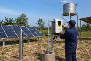
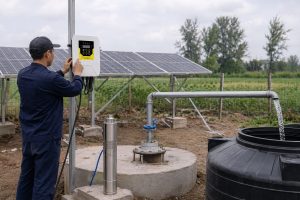
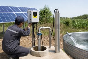
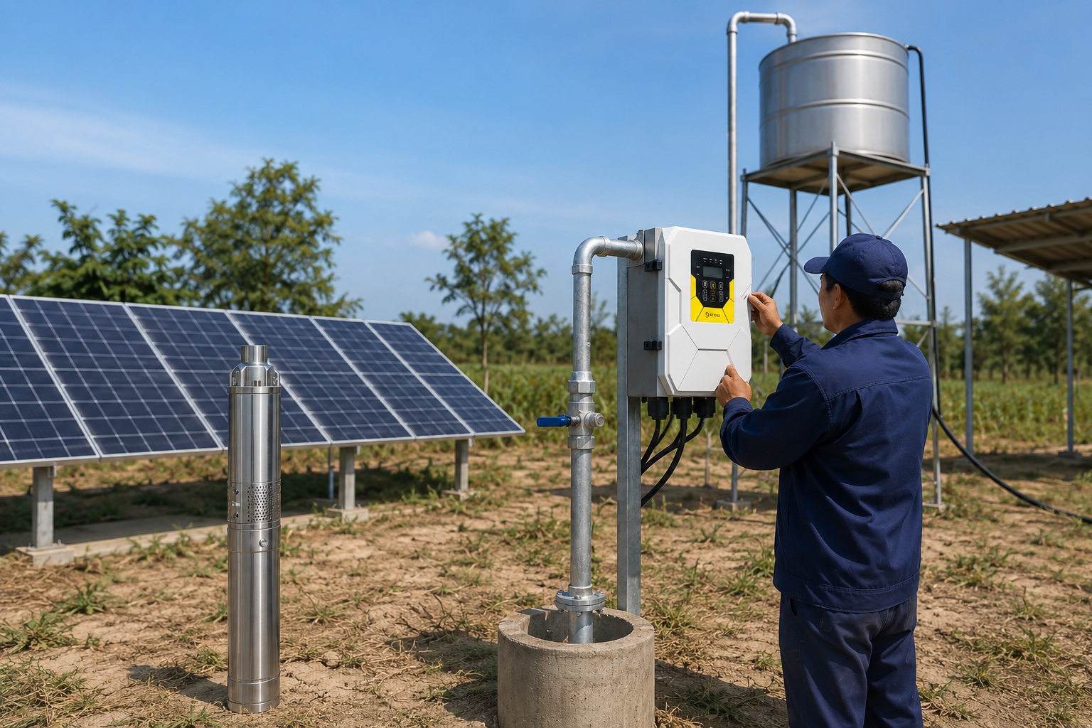
## What About Solar Pumps?****
Want to be free from the power grid?
Solar pumps are a revolutionary solution for off-grid water.
But their selection involves unique factors.
Solar pumps pair specialized pump ends with ultra-high-efficiency BLDC motors. They come in types like screw pumps (high head, low flow) or centrifugal pumps (high flow). Sizing still uses GPM and TDH, but also involves matching the pump's power to the solar panel array.
With growing demand for sustainable solutions, solar water pumps are becoming essential in off-grid regions worldwide.
They offer water independence, are environmentally friendly, and prove highly cost-effective over their lifespan.
The magic behind these systems is not just the pump itself, but the synergy between a highly efficient motor and an intelligent controller.
Understanding these components is key to appreciating their value and selecting the right system for distributors and end-users alike.
Let's explore the core technologies that make these pumps so competitive.
The Power Behind Solar: BLDC Motors
The heart of a modern solar pump is its motor.
These systems use a Brushless DC (BLDC) permanent magnet motor.
These motors are a leap in technology, boasting efficiencies often exceeding 90%.
This is a significant improvement over traditional AC motors, which might be only 60-70% efficient.
The rotor is constructed with powerful rare-earth magnets.
This high efficiency means the pump can do more work with less power.
As a result, you need fewer solar panels to run the system, which directly reduces the initial investment cost.
The design is also more compact and lightweight—up to 47% smaller and 39% lighter than a comparable AC motor—simplifying installation.
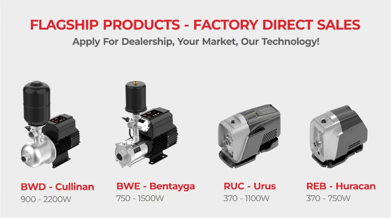
Choosing Your Solar Pump Type
Solar pumps are tailored for specific water conditions, offering a complete product portfolio.
The pump end, which is the part that actually moves the water, comes in several designs.
| Pump Type | Best For | Flow/Head | Key Advantage | Typical Application |
|---|---|---|---|---|
| Solar Screw Pump | Deep wells, low yield | Low Flow / High Head | High sand resistance, extreme lift | Domestic water, livestock watering in remote areas |
| Solar Plastic Impeller Pump | Moderate depths, high volume | High Flow / Medium Head | Excellent wear-resistance, economical | Farm irrigation, pasture water supply, gardens |
| Solar Stainless Steel Impeller Pump | Corrosive water | High Flow / Med-High Head | Superior corrosion resistance, long-term durability | Acidic or alkaline water, high-end homes |
This flexibility allows a distributor to meet a wide range of customer needs, from a small household well in Africa to a large cattle ranch in Australia.
The Brains of the Operation: MPPT Controllers
An intelligent controller is just as important as the pump and motor.
Modern solar pump systems use an MPPT (Maximum Power Point Tracking) controller.
This controller constantly adjusts the electrical load to extract the maximum amount of power available from the solar panels, no matter the sun conditions.
This can boost the water output by up to 30% over the course of a day compared to a system without MPPT.
Advanced controllers also offer a hybrid AC/DC input.
This means the system can automatically switch to grid power or a generator when solar energy is insufficient, such as on cloudy days or at night.
This feature guarantees a reliable, 24/7 water supply, which is a powerful selling point.
## Must-Have Pump Accessories for a Complete Setup****
A pump by itself is not a complete system.
Forgetting key accessories will cause poor performance and pump failure.
Let's review the essential components.
For a reliable installation, you need a foot valve to keep the pump primed, a non-collapsible suction hose, and a strainer (basket or Y-strainer) to block debris. These small, inexpensive parts are critical for protecting your much larger pump investment.
Installing a pump correctly involves more than just connecting pipes.
A set of carefully chosen accessories is required to protect the pump, ensure it operates correctly, and make the system easy to maintain.
These components are not optional add-ons; they are integral parts of a professional-grade installation.
Skipping them to save a small amount of money upfront is a false economy that will almost certainly lead to costly repairs and downtime later.
Let's look at the critical accessories every centrifugal pump installation should have.
Protecting Your Pump
The number one goal is to keep the pump safe from debris and from running dry.
-
Foot Valve: This is a type of check valve installed at the very end of the suction line. When the pump turns off, the foot valve closes, holding water in the suction pipe and pump. This keeps the pump "primed" and ready for the next start-up.
-
Inlet Screen / Basket Strainer: These filter out large debris like leaves, twigs, and stones before they can enter and damage the pump. A simple inlet screen is used for dirty water sources like ponds, while a larger basket strainer is better for cleaner water sources.
-
Y-Strainer: This is an inline filter that can be installed on the suction line to catch finer debris. Its "Y" shape allows collected debris to be easily flushed out through a drain port without disassembling the pipe.
Connecting Your Pump
The pipes connected directly to the pump are critical for its performance.
-
Suction Hose/Pipe: The line drawing water into the pump must be rigid and non-collapsible to withstand the vacuum force. It is crucial that this pipe is the same size or one size larger than the pump's inlet port. Never reduce the pipe size on the suction side. Also, provide a straight run of pipe, at least 5-10 times the pipe's diameter, directly before the pump inlet to ensure smooth, non-turbulent flow.
-
Discharge Hose/Pipe: The options for the outlet side of the pump are more flexible. The material can be PVC, polyethylene, or layflat hose, depending on the application. The size of this pipe will affect the friction loss in your system.
Automating Your Pump
For irrigation, you want the pump to turn on and off automatically with your sprinklers.
-
Pump Start Relay (Startbox): This is an electrical relay that connects your irrigation controller to your pump. When the controller starts a watering zone, it sends a low-voltage signal to the relay, which then closes a circuit to send high voltage (110V or 220V) to power the pump.
-
Smart Controls (Smartbox): These advanced relays provide the same on/off function but also include built-in pump protection features. They use sensors to detect problems like a loss of prime or run-dry conditions and will automatically shut down the pump to prevent motor damage, providing significant peace of mind.
Conclusion
Sizing a pump requires calculating GPM and TDH.
Working backward from your application and using a pump curve chart ensures you select the most efficient and durable pump for the job.
FAQs
Can a pump be too big for a well?
Yes. An oversized pump can rapidly cycle on and off, which will burn out the motor. It also wastes significant energy and can deplete the well's water level too quickly.
How far can a 1 HP pump push water?
This depends entirely on the pump's design. A high-pressure, low-flow 1 HP pump may push water over 500 feet vertically, while a high-flow model might only manage 50 feet.
Does a smaller pipe increase water pressure?
No, this is a common myth. A smaller pipe increases friction and velocity, which actually reduces the effective pressure delivered at the outlet.
What happens if TDH is too high for a pump?
The pump will fail to deliver the required flow rate. It will operate outside its efficiency curve, leading to overheating, excessive wear on components, and a much shorter operational lifespan.
How many GPM do I need for my house?
A general rule for an average 3-4 bedroom home is 10-12 GPM. For a more accurate number, count your fixtures and estimate how many will be used simultaneously.
Do I need a check valve with a submersible pump?
Most submersibles have a built-in check valve. However, installers often add another check valve in the drop pipe every 100-200 feet to help prevent water hammer and backspin.